Exclusive OR Gate (XOR Gate): Truth Table, and Applications introduces a useful concept in digital electronics, computer science, and digital systems.
The exclusive OR gate, also called the XOR gate or Ex-OR, is a basic logic gate that performs a logical operation. It produces a true output when inputs are different inputs, making its exclusive OR definition clear through a truth table.
Unlike other logic gates, XOR helps handle logical choices in circuits and digital circuits. In programming and computing, it supports calculations, helps compare values, and assists with error detection and the ability to control digital signals. These uses show why its simple behavior matters.
For everyday examples, XOR can represent a choice where only one condition should be true. Its meaning, origin, spelling differences, and common mistakes can cause confusion. Still, usage trends show its continuing value in digital technology.
Quick Answer:
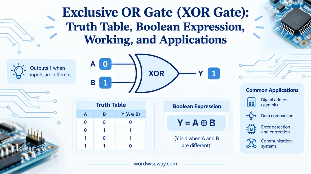
An Exclusive OR gate (XOR gate) is a digital logic gate that produces an output of 1 when its inputs are different and an output of 0 when its inputs are the same.
For two inputs, A and B, its behavior is:
- 0 XOR 0 = 0
- 0 XOR 1 = 1
- 1 XOR 0 = 1
- 1 XOR 1 = 0
The Boolean expression for a two-input XOR gate is:
A ⊕ B = A̅B + AB̅
The symbol ⊕ represents the XOR operation.
A useful way to remember it is:
Different inputs → 1
Same inputs → 0
XOR Gate Symbol and Logic Diagram
The XOR gate looks similar to an OR gate, but it has one important visual difference. An XOR symbol includes an additional curved line on the input side.
This extra curve distinguishes the XOR gate from the ordinary OR gate in circuit diagrams.
A standard two-input XOR gate has:
- Input A
- Input B
- One output
- An additional curved line before the main gate shape
The output is usually represented as Y, giving the relationship:
Y = A ⊕ B
The symbol itself doesn’t tell you the entire operation. You still need the truth table to understand how every possible input combination behaves.
Truth Table
A two-input XOR gate has four possible input combinations. The following truth table shows its complete behavior.
| Input A | Input B | XOR Output |
| 0 | 0 | 0 |
| 0 | 1 | 1 |
| 1 | 0 | 1 |
| 1 | 1 | 0 |
The first row produces 0 because both inputs are the same.
The second row produces 1 because the inputs are different. The third row also produces 1 for the same reason.
Finally, both inputs are 1 in the fourth row. Since they match, the XOR output returns to 0.
This makes XOR fundamentally different from an OR gate.
How Does an XOR Gate Work?
An XOR gate checks whether its inputs have different binary states. Think of it as a tiny digital referee asking, “Do these inputs disagree?”
If they do, the gate outputs 1. If they don’t, it outputs 0.
XOR With Two Inputs
Consider two inputs, A and B.
When both inputs are LOW, the gate sees identical values:
0 ⊕ 0 = 0
When A is LOW and B is HIGH, the inputs differ:
0 ⊕ 1 = 1
The same happens when A is HIGH and B is LOW:
1 ⊕ 0 = 1
When both inputs become HIGH, they match again:
1 ⊕ 1 = 0
This behavior makes XOR particularly useful whenever a digital circuit needs to detect a difference between two binary states.
XOR as a Difference Detector
One of the easiest ways to understand an XOR gate is to treat it as a difference detector.
Suppose two digital signals represent two switches. If both switches have the same state, XOR produces 0. If only one switch is active, XOR produces 1.
For example:
| Switch A | Switch B | XOR |
| Off | Off | 0 |
| Off | On | 1 |
| On | Off | 1 |
| On | On | 0 |
This property becomes useful in circuits that need to detect whether corresponding binary values differ.
XOR Gate vs OR Gate
The XOR and OR gates often cause confusion because their outputs match for three of the four possible two-input combinations.
The difference appears when both inputs are 1.
An OR gate produces 1 whenever at least one input is 1. An XOR gate produces 1 only when the inputs are different.
| Input A | Input B | OR | XOR |
| 0 | 0 | 0 | 0 |
| 0 | 1 | 1 | 1 |
| 1 | 0 | 1 | 1 |
| 1 | 1 | 1 | 0 |
That final row is the key.
OR asks: Is at least one input 1?
XOR asks: Are the inputs different?
The distinction becomes especially important when designing digital circuits.
Boolean Expression
The standard Boolean expression for a two-input XOR gate is:
A ⊕ B = A̅B + AB̅
This expression contains two main terms:
- A̅B means A is 0 while B is 1.
- AB̅ means A is 1 while B is 0.
The OR operation combines these two conditions.
Therefore, the output becomes 1 when either input differs from the other.
This expression also reveals how XOR can be constructed from basic logic gates.
XOR Gate From Basic Logic Gates
An XOR gate doesn’t have to exist as a single physical gate. You can construct its logic using combinations of simpler gates.
The Boolean expression provides the blueprint:
A ⊕ B = A̅B + AB̅
A basic implementation uses:
- Two NOT gates
- Two AND gates
- One OR gate
The first AND gate handles the condition where A = 0 and B = 1.
The second AND gate handles the condition where A = 1 and B = 0.
The OR gate then combines those two possible conditions.
XOR Using AND, OR, and NOT Gates
The construction works like this:
- Invert A to obtain A̅.
- Invert B to obtain B̅.
- Use one AND gate for A̅B.
- Use another AND gate for AB̅.
- Feed both AND outputs into an OR gate.
The final output is the XOR function.
This implementation demonstrates an important principle of digital logic: complex gates can be built from simpler gates.
XOR Using NAND Gates
NAND gates are called universal gates because you can build many other logic functions from NAND gates alone.
A two-input XOR function can be constructed using four NAND gates.
A common arrangement first combines the two inputs with NAND operations and then processes those intermediate results through additional NAND gates. The resulting output follows the XOR truth table.
This matters in digital hardware because designers can sometimes simplify manufacturing or circuit architecture by relying on a limited set of gate types.
XOR Using NOR Gates
XOR can also be constructed using NOR gates. Like NAND, NOR is a universal gate.
The implementation requires multiple NOR gates arranged to reproduce the XOR Boolean function.
Although the circuit arrangement differs from the NAND version, the final truth table remains identical.
XOR Gate With More Than Two Inputs
XOR becomes even more interesting when a circuit contains three or more inputs.
For multiple inputs, XOR produces 1 when an odd number of inputs are 1.
Consider three inputs:
0 ⊕ 1 ⊕ 0 = 1
Only one input is 1, so the result is 1.
Now consider:
1 ⊕ 1 ⊕ 1 = 1
Three inputs are 1. Three is odd, so the result is again 1.
But:
1 ⊕ 1 ⊕ 0 = 0
Two inputs are 1. Two is even, so the output becomes 0.
This odd-parity behavior is one of XOR’s most important properties.
XOR Gate as a Parity Detector
A parity detector checks whether a group of binary bits contains an odd or even number of 1s.
XOR naturally performs this type of operation.
For example:
1 ⊕ 0 ⊕ 1 ⊕ 0 = 0
There are two 1s, which is an even number.
Now consider:
1 ⊕ 1 ⊕ 1 ⊕ 0 = 1
There are three 1s, which is odd.
This relationship makes XOR useful in parity generators and parity checkers.
Even and Odd Parity
Parity systems can use an additional parity bit to help detect certain transmission errors.
For example, if a system uses even parity, the parity bit is selected so the total number of 1s becomes even.
XOR can calculate the required parity relationship efficiently.
However, parity has a limitation. A simple parity system can detect many single-bit errors, but it cannot identify every possible multi-bit error. If an even number of bits change, the overall parity can remain unchanged.
That’s why parity should be viewed as a useful error-detection technique rather than a complete error-correction system.
XOR Gate in Digital Circuits
The XOR gates appear throughout digital electronics because binary addition, comparison, and parity operations naturally depend on detecting differences.
XOR in Half Adders
A half adder adds two single binary bits.
It produces two outputs:
- Sum
- Carry
The XOR gate generates the Sum output.
The AND gate generates the Carry output.
| A | B | Sum (XOR) | Carry (AND) |
| 0 | 0 | 0 | 0 |
| 0 | 1 | 1 | 0 |
| 1 | 0 | 1 | 0 |
| 1 | 1 | 0 | 1 |
Notice what happens when both inputs are 1.
The XOR output becomes 0 because the inputs match. The AND output becomes 1 because both inputs are HIGH.
Together, those outputs represent the binary result of adding 1 + 1:
1 + 1 = 10₂
The XOR supplies the 0 in the least significant position, while the AND gate supplies the carry.
XOR in Full Adders
A full adder extends the half-adder concept by including a carry input.
The sum output can be expressed as:
Sum = A ⊕ B ⊕ Cin
Here, Cin represents the incoming carry.
Full adders form larger binary arithmetic circuits by connecting multiple stages together. Modern processors use much more sophisticated arithmetic structures, but the underlying logic still relies heavily on Boolean operations and binary addition principles.
XOR in Digital Comparators
XOR gates can compare corresponding bits of two binary numbers.
When two corresponding bits differ, XOR produces 1. When they match, XOR produces 0.
For example:
A = 1010
B = 1000
Compare the bits:
| A | B | XOR |
| 1 | 1 | 0 |
| 0 | 0 | 0 |
| 1 | 0 | 1 |
| 0 | 0 | 0 |
The XOR outputs show exactly where the two bit patterns differ.
Additional logic can then combine those results to determine whether the complete binary values are identical.
In Error Detection
Digital information often travels through systems where unwanted changes can occur.
XOR contributes to error-detection mechanisms by calculating parity and checking relationships between bits.
For instance, a parity generator can combine several data bits through XOR operations. A receiving circuit can perform another XOR-based calculation to determine whether the expected parity relationship still holds.
This approach doesn’t tell the receiver everything about an error. It can indicate that a problem occurred without necessarily identifying or correcting the corrupted bit.
That distinction matters in real communication systems.
XOR Gate Applications
The XOR gate appears in many areas of digital electronics and computing.
Common applications include:
- Half adders
- Full adders
- Parity generators
- Parity checkers
- Digital comparators
- Error-detection circuits
- Binary arithmetic
- Bit manipulation
- Data processing
- Encoding and decoding circuits
- Programmable logic systems
- Digital communication circuits
The same basic operation keeps returning: determine whether binary states differ.
Computer Programming and Bitwise Operations
The hardware XOR operation has a close counterpart in programming called bitwise XOR.
A bitwise XOR compares corresponding bits in binary values.
For example:
1010 XOR 1100 = 0110
Each bit position follows the same XOR rule:
| Bit A | Bit B | Result |
| 1 | 1 | 0 |
| 0 | 1 | 1 |
| 1 | 0 | 1 |
| 0 | 0 | 0 |
Many programming languages provide a bitwise XOR operator, commonly written as ^.
Bitwise XOR can be useful for:
- Toggling selected bits
- Comparing bit patterns
- Applying binary masks
- Manipulating flags
- Implementing low-level algorithms
- Performing certain data-processing operations
Hardware XOR gates provide the physical logic that makes these binary operations possible inside digital systems.
Properties
XOR has several Boolean properties that make it especially useful in circuit design.
Commutative Property
The order of the inputs doesn’t matter:
A ⊕ B = B ⊕ A
For example:
0 ⊕ 1 = 1
and:
1 ⊕ 0 = 1
Both produce the same result.
Associative Property
XOR can also be grouped in different ways without changing the result:
(A ⊕ B) ⊕ C = A ⊕ (B ⊕ C)
This property is useful when several XOR gates are connected together.
Identity Property
XOR with 0 leaves the original value unchanged:
A ⊕ 0 = A
So:
1 ⊕ 0 = 1
and:
0 ⊕ 0 = 0
Complement Property
XOR with 1 inverts the original value:
A ⊕ 1 = A̅
Therefore:
0 ⊕ 1 = 1
and:
1 ⊕ 1 = 0
This makes XOR useful for controlled bit toggling.
Self-Inverse Property
Any value XORed with itself produces zero:
A ⊕ A = 0
For example:
1 ⊕ 1 = 0
This property has important uses in binary algorithms and digital logic.
XOR Gate vs Other Logic Gates
Each logic gate follows its own rule.
| Logic Gate | Basic Output Condition |
| AND | Output is 1 when all inputs are 1 |
| OR | Output is 1 when at least one input is 1 |
| NOT | Output is the inverse of the input |
| NAND | Inverse of AND |
| NOR | Inverse of OR |
| XOR | Output is 1 when inputs differ |
| XNOR | Output is 1 when inputs are equal |
Knowing the central rule for each gate makes truth tables much easier to understand.
XOR vs XNOR Gate
An XNOR gate is the complement of an XOR gate.
XOR produces 1 when inputs differ. XNOR produces 1 when inputs match.
| A | B | XOR | XNOR |
| 0 | 0 | 0 | 1 |
| 0 | 1 | 1 | 0 |
| 1 | 0 | 1 | 0 |
| 1 | 1 | 0 | 1 |
You can remember the distinction this way:
XOR = difference
XNOR = equality
That makes XNOR particularly useful when a circuit needs to determine whether two binary values match.
Advantages and Limitations of XOR Gates
XOR gates offer several useful characteristics.
Advantages
- Detect differences between binary inputs.
- Generate the sum bit in half adders.
- Support parity calculations.
- Help compare binary data.
- Provide convenient bit-toggling behavior.
- Work well with other logic gates.
- Can be constructed from universal gates such as NAND and NOR.
Limitations
- XOR alone cannot perform complete binary addition.
- It doesn’t identify which input differs.
- Simple parity checking cannot detect every multi-bit error.
- Larger XOR networks can introduce propagation delay.
- Complex arithmetic circuits require additional gates and control logic.
The limitations don’t make XOR less useful. They simply define where it fits within a larger circuit.
XOR Gate Propagation Delay
Real electronic gates don’t change their outputs instantaneously.
When an input changes, the circuit requires a small amount of time before the corresponding output settles. This interval is called propagation delay.
In a simple circuit, the delay may have little practical significance. However, when many logic gates operate in sequence, delays can accumulate.
Designers therefore consider propagation delay when building high-speed digital systems. The exact delay depends on the technology, logic family, operating conditions, load, and specific device.
This is one reason datasheets matter when selecting actual XOR gate hardware.
XOR Gate ICs and Hardware Implementations
XOR functions are available in standard digital logic families and integrated circuits.
For example, members of the 74-series logic family include devices designed to perform XOR operations. CMOS logic families also provide XOR functionality.
When working with a physical IC, don’t rely on the gate name alone. Check the manufacturer’s datasheet for:
- Pin configuration
- Supply-voltage requirements
- Input voltage limits
- Output characteristics
- Propagation delay
- Operating temperature
- Number of gates inside the package
The exact specifications vary between devices, so the datasheet is the authoritative source for a particular IC.
Real-World Example
Imagine a system with two switches controlling a warning indicator.
The indicator should turn on when exactly one switch is active. If both switches are off, it stays off. If both are on, it also stays off.
That’s classic XOR behavior.
| Switch A | Switch B | Indicator |
| Off | Off | 0 |
| Off | On | 1 |
| On | Off | 1 |
| On | On | 0 |
The important phrase is exactly one.
An OR gate wouldn’t work for this requirement because OR produces 1 when both switches are active. XOR deliberately excludes that case.
How to Make an XOR Gate From Basic Gates
You can construct an XOR function using AND, OR, and NOT gates.
Start with the expression:
A ⊕ B = A̅B + AB̅
Then create the two possible difference conditions.
The first path detects:
A = 0 and B = 1
The second path detects:
A = 1 and B = 0
Finally, an OR gate combines both paths.
The result is 1 only when one input is HIGH and the other is LOW.
This construction is useful for students because it connects three things that can otherwise seem unrelated: Boolean algebra, truth tables, and physical logic gates.
How to Solve XOR Logic Problems
When you encounter an XOR problem, don’t guess from the gate’s appearance. Follow a consistent process.
Identify the Inputs
Write down every input and its binary state.
For example:
A = 1
B = 0
Apply the XOR Rule
Ask whether the inputs are different.
Here, 1 and 0 differ, so:
A ⊕ B = 1
Build a Truth Table
For a two-input problem, list all four possible combinations. For three inputs, there are eight combinations.
This removes ambiguity and makes the circuit easier to verify.
Simplify the Boolean Expression
If the problem gives you a Boolean equation, use Boolean algebra to simplify it.
For XOR, remember:
A ⊕ B = A̅B + AB̅
Verify the Output
Finally, compare your calculated result with the expected truth-table behavior.
If the inputs match, XOR must produce 0. If they differ, XOR must produce 1.
Common Mistakes
Confusing XOR With OR
This is the most common mistake.
OR produces 1 when both inputs are 1. XOR produces 0 in that situation.
Assuming XOR Means “At Least One”
“At least one” describes the basic behavior of OR.
XOR instead means one input differs from the other for a two-input gate.
Forgetting the Odd-Parity Rule
For multiple inputs, XOR produces 1 when an odd number of inputs are 1.
That rule becomes essential when working with parity circuits.
Confusing XOR With XNOR
XOR detects difference.
XNOR detects equality.
Their outputs are opposites for the same inputs.
Treating XOR as a Complete Adder
XOR generates the sum bit in a half adder, but it doesn’t generate the carry by itself.
The AND gate handles the carry in a basic half-adder circuit.
Read More: Hookie or Hooky: Correct Spelling, Meaning, and Usage
FAQs
What is an Exclusive OR gate?
An Exclusive OR gate, commonly called an XOR gate, produces a true output when its inputs have different values. It produces a false output when the inputs are the same.
How does an XOR gate work?
An XOR gate compares its inputs and checks whether they differ. With two inputs, the output becomes 1 when one input is 1 and the other is 0.
What is the difference between XOR and OR gates?
An OR gate produces 1 when at least one input is 1. An XOR gate produces 1 only when the inputs are different, so two 1 inputs produce 0.
What does XOR mean in digital electronics?
XOR means Exclusive OR. The word “exclusive” indicates that the gate accepts the condition where one input is true while the other is false.
What is the truth table of an XOR gate?
For two inputs, an XOR gate has four possible combinations: 00 produces 0, 01 produces 1, 10 produces 1, and 11 produces 0.
Where are XOR gates used?
XOR gates appear in digital circuits, computers, calculators, communication systems, and error-detection circuits. They are useful whenever a system needs to identify different input states.
Can an XOR gate have more than two inputs?
Yes. An XOR gate can work with multiple inputs. The output is typically 1 when an odd number of inputs are 1, depending on the circuit design.
Why is XOR important in computer programming?
XOR provides a useful logical operation for comparing binary values and manipulating bits. Programmers can use it in algorithms, bitwise operations, and certain error-checking processes.
What is another name for an XOR gate?
XOR is also written as Ex-OR or Exclusive OR. These terms refer to the same logical operation, although “XOR gate” is the most common form in technical writing.
Why does an XOR gate produce 0 when both inputs are 1?
Both inputs being 1 means they are equal. Because XOR produces a true output only when its inputs differ, the combination 11 produces 0.
Conclusion
An Exclusive OR gate (XOR gate) may follow a simple rule, but its role in digital systems is far from trivial. By producing a true output only when inputs differ, it gives computers and electronic circuits a clear way to compare binary conditions.
Once you understand its truth table, XOR becomes much easier to recognize in real applications. From digital circuits and programming to calculations and error detection, this small logic gate supports many tasks behind the scenes.
Learning XOR also makes it easier to understand more advanced digital electronics. Its simple behavior is one of the building blocks that helps turn basic binary choices into useful computing operations.

Emma Smith has dedicated 14 years to Princeton University’s English Department, mentoring students in textual interpretation, literary movements, and critical frameworks. Her research explores Shakespearean drama, Victorian serial fiction, postcolonial narrative theory, and manuscript studies and probing how literary forms evolve across cultures and centuries. Emma has delivered lectures at international humanities congresses and published findings in distinguished academic journals, underscoring her commitment to scholarly depth and vibrant teaching.